
Dwave Systems will have a new 128 qubit quantum computer in about two weeks. This was first discussed four days ago on this site along with a review of the background on the Dwave adiabatic quantum computer.
In the systems Dwave builds, the maximum number of connections per qubit is constrained by noise. In order to couple a qubit into a coupler, the qubit needs a certain amount of inductance. This inductance is obtained by increasing the perimeter of the qubit, which increases the noise seen by the qubit. Increasing the noise a qubit sees has several deleterious effects, all of which I will be discussing in later posts. For now let’s just say that the maximum number is 6 connections per qubit without answering the question of why or how to make it better.
Given 6 connections per qubit, what is the “ideal” layout / interconnect scheme? Answering this depends on what as a designer you are trying to optimize. Let’s say that the primary objective is to make a tile-able unit cell with a maximum of 6 connections per qubit. There are several possible ways to do this. The way we settled on is as follows:
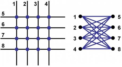
The qubits are topologically loops of niobium. They are interrupted in a variety of places by compound Josephson junctions. Imagine drawing four loops schematically like the outlines of four parallel popsicle sticks lying north-south, and then laying down on top of this the exact same structure rotated by 90 degrees. Each “popsicle stick outline” is a single qubit. The points of intersection are where the coupling devices are placed. This unit cell looks physically like the picture on the left, which is identical to the picture on the right, which is also known as the complete bipartite graph on 4 vertices K_{44}.
From Geordie, DWave Systems CTO comments:
For the 128-qubit chip, you can split the chip into two regions, the 6 upper right hand blocks and the 10 lower left + diagonal blocks. You can embed a K_{8} in the upper right block, and a K_{12} in the lower left+diagonal block. These two complete graphs can be connected in a limited way through the couplers the two sections share. Since the size of the fully connected graphs you can embed in this guy is small, we plan to operate based on algorithms that respect the interconnect structure of the 128-qubit chip, ie. graph embedding can be done at this level but the cost is prohibitive at this stage.In principle you can continue to tile the plane with unit cells until you (a) run into fab yield limits and/or (b) run out of real estate on the processor die. You could build a 256-qubit chip by tiling two 128-qubit patterns side by side, or a 512-qubit chip by doing a 2×2 tile of the 128-qubit pattern, or a 2,048-qubit chip by doing a 4×4 tile of the 128-qubit pattern. Re. timing on the entanglement results, as soon as possible.

So in this design there are 8 qubits per unit cell, 16 inter-cell couplers per unit cell, and 8 intra-cell couplers (4 to the right, 4 to the bottom). To make the tiling strategy explicit, here are 32-qubit.


Brian Wang is a Futurist Thought Leader and a popular Science blogger with 1 million readers per month. His blog Nextbigfuture.com is ranked #1 Science News Blog. It covers many disruptive technology and trends including Space, Robotics, Artificial Intelligence, Medicine, Anti-aging Biotechnology, and Nanotechnology.
Known for identifying cutting edge technologies, he is currently a Co-Founder of a startup and fundraiser for high potential early-stage companies. He is the Head of Research for Allocations for deep technology investments and an Angel Investor at Space Angels.
A frequent speaker at corporations, he has been a TEDx speaker, a Singularity University speaker and guest at numerous interviews for radio and podcasts. He is open to public speaking and advising engagements.