

A guest column by Joseph Friedlander
(The illustrations in this article were done with the help of Sketchup and using parts of models from the 3d Warehouse (hat tip!))
Hi, folks.
On the principle of Six Degrees of Separation—the concept that any person in the world can be reached by someone who knows someone—I am indulging in a double leap of faith because of the emergency in the Gulf of Mexico. I am betting both that this idea is good and that someone who knows someone will read it and pass the idea on.
UPDATE: After cutting the riser, BP has placed a heated top hat dome over the leak. There is still leakage. The effectiveness of this procedure will be more clear over the next day or two.
Business Week reports that the current design could capture over 90% of the leaking oil. Optimization of the next day or two will determine the level of success.
END UPDATE
Deepwater horizon oil spill volume and extent from wikipedia
Bluntly, the problem may be over by the time you read this—or it may go on for a very long time indeed.
Everyone hopes the relief wells will work—but it would be nice to have an emergency backup plan in case the leak has nine lives. (The most worrying possibility to me—from volcanic explosions we know that when pressure begins to be relieved is sometimes the time to worry. Gas can come out of suspension, leading to explosions. As unlikely as total wellhead failure is—it’s something we could use a counter against.) As hurricane season in the Gulf of Mexico is from June 1 to the end of November, people are already speculating on ‘Oilgeddon’…
Lack of detailed data on the disaster site.
I have only one criticism of BP that I want to vent publicly: In the situation they are in, it would have been logical to release a site map of the detailed configuration of the sea floor near the broken pipes and leaks as well as dimensions and specifics (example: Thicknesses, grades of pipe, etc) of the site. There is no way to offer coherent advice without knowing these basic facts. I have no real idea of the distances between the leaks, the precise geometry of the bent riser (and the rotary orientation of the three leaks) nor the extent of the debris fields. It would be nice to know peak pressures known to be coming out of the pipes, and so on. Maps should be released and updated after each major equipment shuffle, in case anyone has an idea. For lack of such a document, there may be errors in this presentation; I hope they are forgiven. Wikipedia in the article above listed the close geometry of the leak (as implied by the size of the containment devices in this quote)
The 4 feet (1.2 m) wide and 5 feet (1.5 m) tall “top hat” dome is much smaller than the first containment dome, which was 40 feet (12 m) tall and 125-tonne (280,000 lb).[121]
as being in the ~1-20 meter range; therefore that is the width of the device detailed later on in this article. Presumably the big dome would have covered all three leaks? Who knows? BP, but I haven’t seen a simple released schematic of the situation…
The device described in this series of articles may prove useful to produce and have on hand in case of future occurrences; literally it would make sense to have quick-assembling kits for each busy offshore drilling area for use in such an emergency within a week after a subsea blowout.
I am writing a public explanation of how this device works with pictures. This is in two parts; the first covers what the invention is and its form and function (and manufacturability). The second part covers details on how it is made, assembled, ‘gotchas’ (technical concerns for the unwary) I will ask Brian to post this first part immediately because of the destruction being wrought. My hope is that someone who knows someone etc. will bring this to the attention of someone in BP, the Coast Guard, Washington, heck, even James Cameron if the spill goes on any longer. This assumes the invention is actually likely to be useful; I leave that to the reader to judge.
The Difficulty of Screening Ideas In A Disaster Situation
I did try submitting an idea but I have no idea if it even hit bottom in the black hole of BP’s evaluation process.
I am assuming BP literally will not know how to process the idea even if it does reach it—because they are being buried alive under suggestions. Even industry pros are having problems being heard. (see http://cbs11tv.com/oilspill/keller.oil.plug.2.1724169.html) Also adding to the noise to signal ratio are ‘helpful’ suggestions by radio talk show hosts looking to have some fun with the help line—and my favorite—the feared Quilt (h/t to him) at this gawker comment link
Proposal: Prevent the oil spill using time travel.
Steps:
1. Invent time travel
2. Travel back in time to before the spill
3. Prevent the spill
4. Place bets at the track
Materials:
Clocks
Flux capacitor
Large hadron collider
Clothing from the year 2010
Girl on your arm ready for adventure
Cheese sticks
Edited by Quilt at 05/29/10 11:32 PM
… steakneggs05/30/10
@Quilt: We’re ready to go. BP so needs us.
Hilarious as I find the above, there are only so many on the BP tech team evaluating these things, so it is entirely possible that—public relations aside– NO ideas are being effectively, seriously considered that are of public origin. Manpower is always the scarcest thing in a crisis.
Here is a web page if you are interested in trying to submit an idea yourself—
http://www.deepwaterhorizonresponse.com/go/doc/2931/546759/
Suggestions
What is being done with submitted suggestions?
Throughout the ongoing response efforts thousands of people across the globe have offered their ideas for stopping the flow of oil into the Gulf, containing or recovering it, or cleaning it up.
BP has established a process to receive and review submitted suggestions, on how to stop the flow of oil or contain the spill emanating from the Mississippi Canyon 252 well. Proposals are reviewed for their technical feasibility and proof of application.
More than 7,800 ideas have been proposed to date. Given this quantity of technical proposals suggested by industry professionals and the public, it may take some time to technically review each one.
All proposals submitted through the process defined below will be reviewed.
Failure to follow the process below will likely delay proposed solutions from being reviewed.
If you want to offer suggestions by phone:
Please call 281.366.5511. After each call, the caller will be sent a simple form to provide details. When the caller completes and submits this form, the proposal is sent to BP technical personnel for review. If you want to offer suggestions online:
A suggestion submission form is available at:
http://www.horizonedocs.com/artform.php
Follow instructions on the form.
For most timely review, please use this process to submit your suggestion.
What happens with your proposal?
• All proposals are reviewed for technical feasibility and application. Given the volume of proposals, this may take some time. A reply will be sent via email or fax to each caller informing them of the technical review outcome.
• Feasible solutions will be forwarded for additional consideration. Callers whose ideas are considered feasible will be advised by email that we will contact them if and when their support is needed.
Unified Command thanks each submitter for their interest and willingness to share their ideas.
Therefore this article is an attempt to get to somebody who can make pass the word along. Even foreign readers may know someone who can speak to some diplomat who… you get the idea. To build even a crude version of this would take a couple weeks of 24/7 with unlimited manpower money and moxie, so the sooner word hits the right place, the better. Now this idea has a URL and a home, so let’s get on with describing it.
I have had an idea, not to stop the oil, but to contain it. I call it the Friedlander Oil Chimney.
I submitted it to BP via their website but frankly their PDF did not like my email system so it told me to mail the attachment it produced. I don’t know if they will see the idea or not, but I believe that without pictures they may have difficulty understanding it.
So here goes—
Let us consider a leak site on the ocean floor.
For an apt description of the difficulties of trying to work down there, see this dailymail article.
Briefly, we can divide between trying to channel the oil (to contain it) and to try to fix the damage. I believe we have to stop trying to fix it and need to capture the oil instead. (Some people have projected as long as the end of the year—even many years to fix it. Alarmist or not, it has already lasted far longer than most folks have thought likely…) If we can capture the oil long term, reliably, even over years, we have time to develop robotic technology that can give us nimble-fingered abilities on the ocean floor or the moon with teleoperated ease. So IF the oil is 100% confined, we don’t actually need to fix the damage on a rush timetable. Better built to last than rigged under fire…
The diameter of the affected site on the sea floor MAY BE as little as 40 feet in diameter. It may be a 2-foot pipe—but there must be clearance around the leak. (Most things that leak got that way for a reason; the event that ruptures a containment vessel usually generates a debris field.) In the event of an extremely high pressure jet escaping, containing that issuing oil will only be possible if the radius of the containment device is far enough away that the ocean water has chance to bring the jet to stagnation or near it. http://en.wikipedia.org/wiki/Stagnation_point

Fig. 1: An unlikely ‘telescopic view’ (forced perspective) showing top of pipe oil leak, naturally spreading oil, and far above, at the surface, a tanker running a line to a tug.
Now let’s pretend—suppose– I have a ‘magic magnet’ aboard that tugboat that attracts the oil so it does NOT disperse and spread with the current, but rides up like a pillar of smoke straight to a designated spot on the surface (around the tug, so it can pump the oil to the waiting tanker)!

Fig. 2: Rather unlikely—a nondispersing ‘pillar of oil’ rising undisturbed through the ocean (also Fig.3. below)
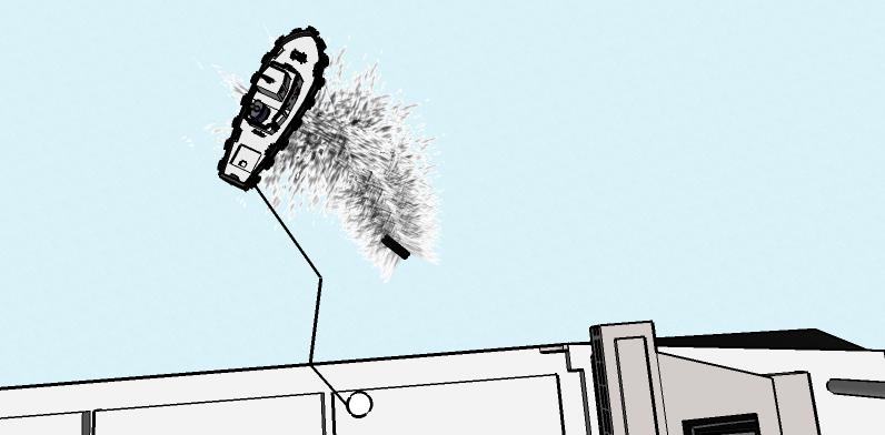
Fig. 3. An above view of the ‘pillar of oil’.
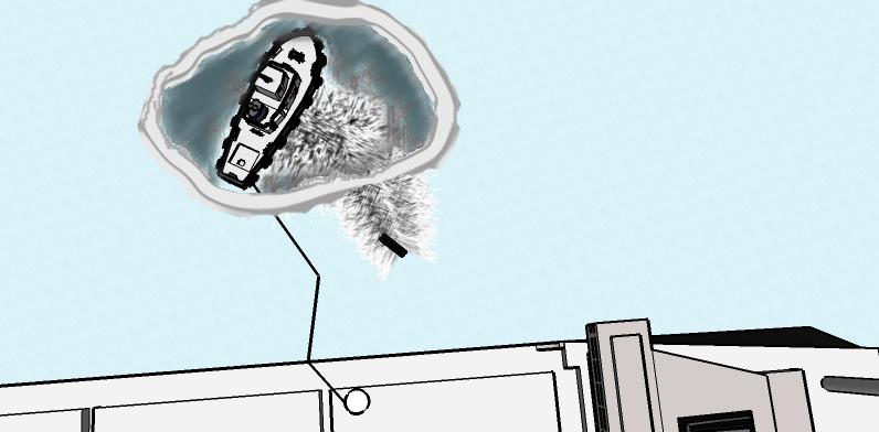
Fig. 4 (above): Let’s add a retainer ring –a floating oil boom– around the pumping tugboat filling the tanker so the oil does not disperse on the surface. The pump can now pump concentrated oil aboard the tanker (with a centrifugal separator).
Now, there is really no ‘magic magnet’ or ‘pillar of oil’. But there are ways to get the practical equivalent.
Follow the sequence—step by step below.
1. Build a sinker crown (pocket crown), (ballast ring) which has a confined space for ballast around an inner hole of sufficient diameter to give clearance for the leak site (in the case illustrated below, a leaking pipe). Note that Fig 5 (below) shows a kind of ring shaped ballast compartment—far easier to build would be a space frame http://en.wikipedia.org/wiki/Space_frame with multiple places or pockets to hold rock (or precast concrete). As the song Mack the Knife says, this ring is just, just for the weight, dear… to keep the whole column from drifting out of position despite the leak generated currents. For ease of deployment ballast may be added either before or after positioning. In the case of dumped small rocks (shown in the pocket’s bottom) it may even be added during the operation to firmly settle this foundational ring on the sea .bottom. And it would be wise to countour it, which is to say (in the space frame variant,) deliberately construct something that fits the touchdown site on a custom-tailored basis, projections where there are hollows, hollows where there are projections. Then lowering it down is a matter of having three floating cranes (with a fourth for spare in case of mishap) position it tension it and lower it, ring by ring—ballast ring first—Fig. 5, below:
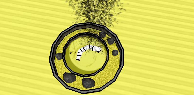
Fig 5—The weighted ballast ring around the leak site. This is lowered first; the (attached!) other parts are omitted for clarity. And the sea bottom is shown in bright tones for clarity. The ballast has been added to the pocket of the ballast ring, weighing it down—under the rocks we may imagine steel plate. (the central part shown with the leaky pipe is exposed sea bottom) Vents near the bottom allow water to displace out. Important, as rising oil is jetting in and in dynamic motion.
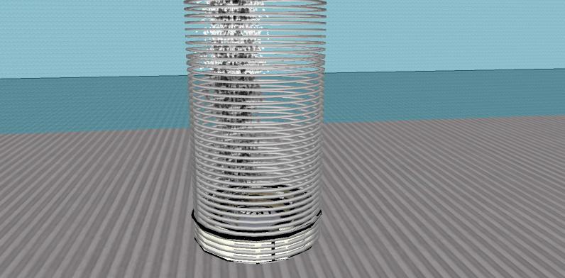
Fig.6 The weighted ballast ring’s more realistic appearance (joined to the containment sleeve). As ring after ring of the confinement sleeve is lowered down, the stack on the surface expands until it reaches full height.
Now we see a less contrasting view in Fig.6 above—in this model the confinement sleeve is designed as an articulated series of rings and bands, the rings being hard and joined with cables, the bands fiber reinforced plastic / cloth. Unlike above, this more realistic view shows the confinement sleeve attached; it is lowered with the bottom ring to the sea bottom from the three floating cranes.
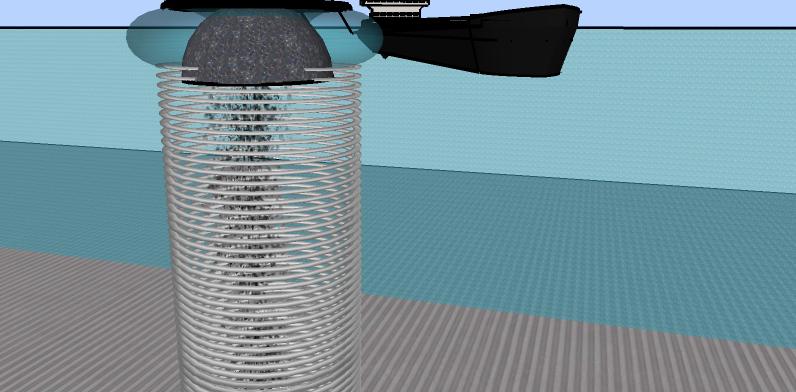
Fig.7—(above) The upper part of the Friedlander Oil Chimney from the side–Continuing up the stack, we see the naturally buoyant escaped oil now trapped within the top, confining hemispherical hollow space within the floating top toroidal (tire-shaped) ring—the floater ring, as it is called, floats above the sinker ring and is joined to them by a reticulated confinement sleeve with both flexibility and plenty of slack. This is necessary to avoid damage during rough seas and heavy surges of current and other flow phenomenae. The whole thing sways like seaweed.
Note that in really rough seas there is a certain amount of ‘slack’—difficulty in securing a tanker during hurricane season in the Gulf of Mexico during the months of June through the end of November—the oil keeps floating up the very long tube (a certain amount of custom tailoring of this device, which I call the Friedlander Oil Chimney—may be necessary for each site—customizing the bottom ring to fit the site, using a smaller diameter confinement sleeve to save on material, (and obviously less length of confinement sleeve for shallower bottom leaks of oil!) –and using a smaller top floater ring to save on costs. The one shown in the picture is huge, but I wanted to illustrate it clearly. It can be in many forms—I chose the torus because it left room for an accumulation dome holding risen oil. But really the only rule is it has to float and endure hurricane winds (and have a light on top) Obviously smaller versions will have less capacity for internal oil storage. And for quick deployment you want the smallest that will do the job. Think less than half the width of the tanker.
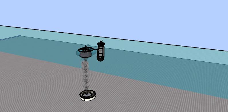
Fig.8—(above) confinement sleeve omitted for clarity, whole view (wider than real, shortened)
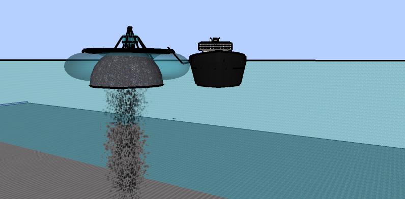
Fig.9—(above) confinement sleeve omitted for clarity, with a clearer view of bouy and safety light tower on top. Inside is the centrifugal separator and pumps and line storage.
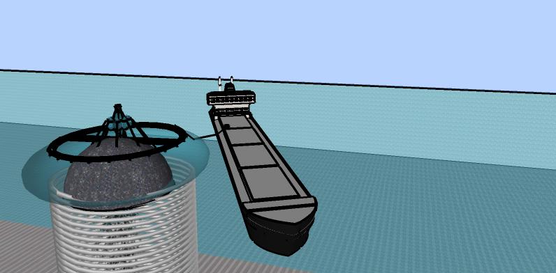
Fig.10—top of Friedlander Oil Chimney-(exaggerated wideness)-
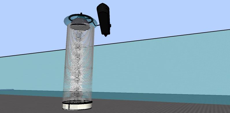
Fig.11—(Above) Side perspective view of Friedlander Oil Chimney.(exaggerated wideness, shortened height). Note the tanker above—if we take the DEEPWATER HORIZON leak on the floor of the Gulf of Mexico as the pattern for the footprint, the true perspective is about 1/5-1/10th the confinement tube diameter (say 30-60 feet) and three times this height plus (around a mile deep) It is shown out of proportion for clarity…
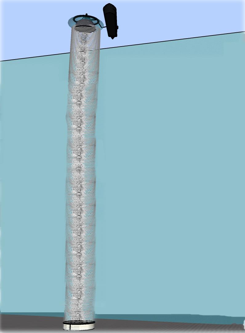
Fig 12. (below) More realistic height view of mile high Friedlander Oil Chimney—still 5-10 times too wide given the 30-60 foot ground print around the damaged pipe. The way it exhibits undulatory motion back and forth is characteristic of a loose buoyant suspension in water. http://en.wikipedia.org/wiki/Lateral_undulation.
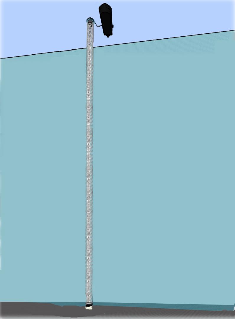
Figure 13 (realistic)—(below) Near truly proportioned Friedlander Oil Chimney for a 40-60 foot wide containment ‘footprint’. The lack of detail visible shows why we explained the features with exaggerated perspective! In rough seas it would bend and sway like seaweed—length is shown tauter than really would be the case. It would really be partly curved as it rose to the surface—not unlike parenthesis “( )” marks. This is how it would ‘look’ in real life kinda, sorta. (for quick buildability it would be more space-frame like on either end, and frankly look like a patchwork in between—rf welded plastic from hundreds of different rolls thrown in on a rush job schedule.)
One thing I don’t have time to illustrate in this first article is the advantage of concentric emplacement—simply put, much larger diameter ones of equal height can be placed around older versions (after reeling them slightly taut for ease of emplacement. Think not of a snake shedding its’ skin but of a snake donning a new skin!
So a Friedlander Oil Chimney can be deployed more than once without removing the first deployed unit (destroying the possibility of leaks during deployment of an upgrade version. Simply, the later tube is larger and is deployed concentrically (outside and enveloping) the old one. Thus there should never be an unprotected moment during replacement. (Yes, plastics—even reinforced– wear out!) Of course partial patching with this method can be done as well…
Deployment is from the surface down, the sinker crown (pocket crown, ballast ring) lowered first and the fan-like sides expanded section after section, ring after ring, as the supporting cables are reeled out and the containment sleeve lengthens. With release of the floater crown into the water, deployment is complete and the escaping oil is confined to inside the ring of the floater crown, where it can be pumped out to arriving tankers. Note that this large tubular sleeve is longer than the deployment site is deep with considerable slack for fluidic displacement and undulation (minimizing stresses)
Manufacturability and deployability questions
A 15 meter diameter containment sleeve tube 2000 meters long (400 meters of slack) will use around 100,000 square meters if fabric/plastic) (if a single layer thick) and around 100 kilometers of reinforcing fibers and cables. With many layers of thickness for endurance and redundancy—these values could go up about 10 times.
If the containment sleeve rings are 200 in number and 10 meters apart, each weighing 10 tons, you have a 2000 ton sleeve, plus the ballast ring plus the floater ring. You could be perhaps 4000 tons in total. To make the first one quickly buildable, floating booms and their joiners could be improvised under a inflatable hemisphere such as Professor Bolonkin has outlined. Oil could be scooped up by a small boat bearing a pump. Later versions could be far more robust, but this is quick. The rings can be spaceframes http://en.wikipedia.org/wiki/Space_frame also holding accordoning and expanding folds of film/cloth. 2000 of these joined assemblies (with interlocking folds to keep the oil in) should be a very large stack, hundreds of feet high (or long, if floated on their side and then dropped vertically down like a deploying Slinky http://en.wikipedia.org/wiki/Slinky)so a floating deployment structure (also used to prestack the rings) must also be built. The whole assembly is lowered from there, with the aid of the floating cranes for positioning.
All this should be buildable (at emergency funding rates on a wartime schedule using far more manual labor than commercially wise) IOC http://en.wikipedia.org/wiki/Initial_operating_capability in a couple weeks (first Friedlander Oil Chimney) but what you want to do is build specialized tools to make subsequent Friedlander Oil Chimney’s cheaper to build.
The tools involved include insertable floating hoses to suck up all oil retained in the containment sleeve. (The oil floats up automatically from the vicinity sea floor, not being able to be dispersed by currents or displacement, literally confined in a plastic chimney as it rises to the sea surface.) Centrifugal separators will be necessary to conserve tank space (and input relatively pure oil) plus access to and use of standard vehicles and personnel deployed now)
To cut and weld the plastic fabric into the containment sleeve we will also needRF welding tables. I took the liberty of writing David B. South of the Monolithic™ Dome Institute of Italy, Texas, with wide and very practical experience in RF welding of plastic fabrics , with attachment points, complicated geometries, etc. At BRUCO they make inflatable Monolithic Airforms http://www.monolithic.com/topics/airforms Airforms for holding up rebar in a dome shape to take sprayed concrete and make domes, tunnels, culverts—these are not simple tarps, though they do make those too—2 acres in extent.
http://www.monolithic.com/stories/bruco-the-caterpillar/photos
Here is detail of how they make tarps. According to David B. South, The automated, laser guided, 230 foot long RF welder http://www.monolithic.com/stories/measuring-seam-strength-in-a-monolithic-airform (radio frequency welder that can heat and seal fabric pieces with microwave—picture on their site http://photos.mydomesite.com/000/002/394/medium/dscf7069.jpg?1250262432 ) can achieve a practical weld speed about half the 25 meters a minute I hypothesized. Monolithic alone has 2 welders and there are others owned by the truck tarp industries that presumably could be mobilized to make the ring barrier toruses of the containment sleeve. Mr. South agreed with my statement that they could sew (join, weld) seams and attachment points –“ The complexity should not be a problem… You are correct. It would not be a problem.”
I thought that CNC programming might be needed (adding to the schedule) but according to Mr. South, “the CNC is used more for complex patterns…” and given the complexities they handle every day in Airforms, it seems probable that the film/fabric parts could be produced with minimal delay; possibly in the Gulf region alone.
As an example, Monolithic has handled 40,000 lb. Airforms (cutting, folding and processing—even packing—a folding inflatable massive tarp like product) and half that weight is routine. Here is a photo on their site showing a rolled, folded, 265-foot half-sphere Airform http://photos.mydomesite.com/000/002/170/medium/file0064.jpg?1245686310 With a space frame approach, the solid parts of the ring should be doable in thousands of welding shops. Then the rings would be assembled and stacked in deployment order. Reinforcement cable would be assembled into a kind of net mesh to keep the thing from tearing underwater under fluid currents and other surge stresses.
They also do huge grain cover tarps. Look at this—it is similar in size to a larger floater crown than would be needed for the BP spill. http://photos.mydomesite.com/000/002/175/medium/pic002.jpg?1245686353 A very impromptu space frame floater ring could be built with floats beneath and such a tent like construction against hurricanes (and buoy tower above). This is for the initial facility. You would eventually want to build a facility to make these things the right way, on which we will close this article.
NOTES FOR THE FUTURE
It is very important to get the leak stopped; but also it would be very nice to get what I call a Maximum Manufacturing Facility out of this—a facility with the ability to make kilometer scale single piece (not ring construction) tubes with a rf welding line and long tube clip and weld capability. This would also have great uses for supertall inflatable towers. This facility would also have an assembly jack pile tower for joining rings, pleats, strips and fanfolds; a finger tower capability, standpipe capability, a hub and spokes line like a Maypole for wrap reinforcement using mesh, a suspension jig for assembling jellyfish like suspended structures…the list goes on.
Such a comprehensive facility would have many uses and make it possible to make a custom 2 kilometer Friedlander Oil Chimney in days, not weeks.
So now we come to the end of this first part of the article. I hope you know someone who you can pass mention of it to who might know someone who can suggest it to BP or anyone else concerned with the Gulf of Mexico.
As David B. South said in closing his kind reply to me, “Good luck to us all…”
So it seems, does the Gulf of Mexico….
Remember, if you know someone who might know someone, feel free to forward the URL of this article https://www.nextbigfuture.com/2010/06/suggestion-on-dealing-with-deepwater.html
The End.

Brian Wang is a Futurist Thought Leader and a popular Science blogger with 1 million readers per month. His blog Nextbigfuture.com is ranked #1 Science News Blog. It covers many disruptive technology and trends including Space, Robotics, Artificial Intelligence, Medicine, Anti-aging Biotechnology, and Nanotechnology.
Known for identifying cutting edge technologies, he is currently a Co-Founder of a startup and fundraiser for high potential early-stage companies. He is the Head of Research for Allocations for deep technology investments and an Angel Investor at Space Angels.
A frequent speaker at corporations, he has been a TEDx speaker, a Singularity University speaker and guest at numerous interviews for radio and podcasts. He is open to public speaking and advising engagements.