

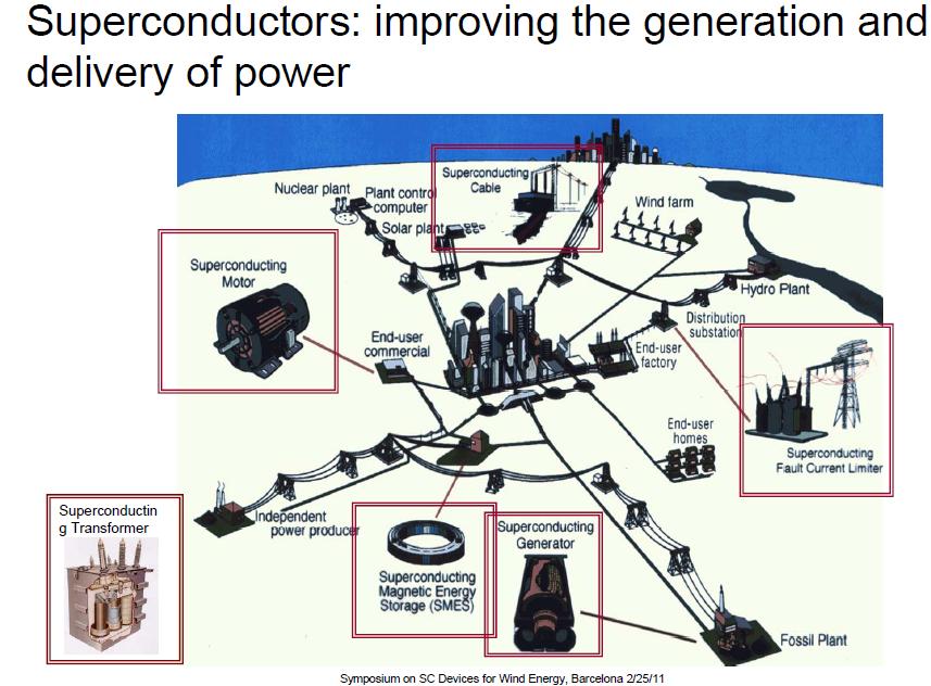
2G HTS Applications Developments (62 pages)
Superpower inc is working on :
1. 2G HTS SMES (High Temperature Superconductor superconducting magnetic energy storage)
2. FCL (Fault Current Limiters) Transformer
3. FCL (Fault Current Limiters)Module Development
4. HTS (High Temperature Superconductor) Cable
5. HTS (High Temperature Superconductor) Generators and Motors
Superconducting magnetic energy storage project
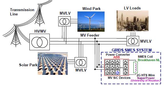
• Energy stored in DC magnetic field (E ~ B2)
• ARPA-E funded proof of concept project recently awarded ($5.2M/3yr)
• Project Participants
– ABB (lead – power electronics / system integration)
– Brookhaven National Laboratory (high field coil design / fabrication)
– SuperPower (2G HTS / coil design support)
– UHouston (enhanced 2G HTS fabrication)
• Storage capability (~2.5 MJ / 20 kwh)
– 25 Tesla coil
– Enhanced power electronics
– over 80% round trip efficiency
• SMES is currently used for short duration (secs) energy storage for improving power quality
• In a utility situation, SMES could be used for either:
− diurnal storage (hours), charged from baseload power at night and meeting peak loads during the day
− medium term storage (minutes) to level out variations in renewable (solar, wind) generation
Components of SMES
• A typical SMES system includes three parts:
– superconducting coil,
– power conditioning system
– cryogenics
• Once the superconducting coil is charged
– With a persistent current switch: the current will not decay and the magnetic energy can be stored indefinitely
– With non-persistence: the current will decay based on the residual resistance in the system
• To charge the coil, the power conditioning system uses an inverter/rectifier to transform AC power from the grid to direct current to power the magnet
• The stored energy can be released back to the network by discharging the coil using the power conditioning system to convert DC back to AC power
• The inverter/rectifier accounts for about 2-3% energy loss in each direction. SMES loses the least amount of electricity in the energy storage process compared to other methods of storing energy
• Other energy storage methods, such as pumped hydro or compressed air have a substantial time delay associated with the energy conversion of stored mechanical energy back into electricity
• In SMES, the main parts are motionless, which results in high reliability
Why high field HTS SMES?
• Energy stored scales as B^2 * r^3, while losses scale as r^2
• 2G HTS enables high field operation for a compact, high energy density system
• Toroidal geometry lessens the external magnetic forces, reducing the size of mechanical support needed
• Fields in a toroidal SMES are mainly axial, maximizing the use of 2G HTS
• Due to the low external magnetic field, toroidal SMES can be located near a utility or customer load
Challenges fro HTC SMES
• High fields equate to high stresses
– mainly hoop stress, 2G HTS can handle up to 700 MPA hoop stress
• High performance conductor required for economics to be competitive with advanced batteries (need to be in the $50/kAm range)
• Persistent current joints / switches highly desirable to reach loss targets
• Long lengths will be required to minimize / eliminate splices / joints (each splice is a loss source)
HTS Transformers for the power grid – half the size and weight

Benefits:
• Greater efficiency
• Smaller, lighter and quieter
• Can run indefinitely above rated power without affecting transformer life
• Do not require cooling oil like conventional transformers, thus eliminating the possibility of oil fires and related environmental hazards and costs
Phase 4: 2010 – 2015 New Project
• FCL transformer being designed and constructed in a $ 21.2 M Smart Grid program
• Partners:
– Waukesha Electric Systems,
– SuperPower,
– University of Houston,
– Oak Ridge National Laboratory
• To be installed Southern California Edison grid by early 2014 (MacArthur Substation)
• 28 MVA (69 kV : 13 kV, 40 MVA overload capability)
• Fault current limiting capability ~ 40 to 50%
Why HTS Transformers?
• HTS transformer development is underway worldwide
– Projects in Japan, Korea, China, India, Australia
• The grid contains a great many transformers
– On average there are 6-8 transformers between a generator and its load
• Many transformers in the grid are aging, creating a ready HTS market
– 110,000 US transformers >10MVA are more than 35 years old
• HTS transformers can save energy and reduce CO2 emissions*
– Even at 99.4% efficiency, transformer losses are 40% of total grid loss because they are so numerous
– If HTS transformer is 0.2% more efficient, losses are reduced by 1/3
– SAVINGS– ~25 TW-hr, with associated 1.5 x 10^7 ton annual CO2 reduction
• Transformer size, weight, fire hazard, and environmental impact reduced.
• Overload operation is possible with no loss of lifetime
• Fault current limiting capability is possible– supports Smart Grid
HTS Fault Current Limiters: New technology for a growing problem

• As new sources of generation are added, utilities are faced with the threat of higher levels of fault current
– HTS Fault Current Limiters (FCLs) address the market pull to cost-effectively correct fault current over-duty problems at the transmission voltage level of 138kV and higher
– The HTS FCLs will reduce the available fault current to a lower, safer level (20%-50% reduction), so that existing switchgear can still protect the grid
• Utility market needs at the transmission level:
– Accommodate increasing fault currents due to added generation
– Prevent breaker failures & associated problems (e.g., welded contacts, bus bracing, etc.)
– Maintain flexibility to accommodate load growth and “open access”
– Avoid adverse side effects imposed by existing solutions
– Reduce “through fault” stresses on aging infrastructure
– Avoid need for expensive 80kA breaker upgrades
• HTS FCLs are a natural complement to AC HTS cable systems
• Discussions with 20+ utilities have consistently validated the need
65% Fault reduction at 1st peak with 2 tape circuit for a prospective of 26kA
Sub-cooled conditions improved 48% voltage (192% increase) and 32% current (132%), a total of ~253% increase in power.
Power transmission cable manufactured by SEI with SuperPower 2G HTS conductor
Benefits
• 5 (AC) to 10 (DC) times more capacity than comparable conventional cables
• Can be used in existing underground conduits saves trenching costs
• Liquid nitrogen coolant is also dielectric medium (no oil)
• Greatly reduced right-of-way (25 ft for 5 GW, 200 kV compared to 400 feet for
5 GW, 765 kV for conventional overhead lines)
• Operating at high currents, can obviate the need for step-up / step down transformers
• Can be used on conventional equipment with minor modifications
HTS Coils for Motors and Generators
Distinct Advantages:
– Improved efficiency, including CRS for cooling the devices
– 50% reduction in full load losses
– Improved power quality enabling faster switching speeds
– 30% – 50% smaller and lighter, heat disposal of less concern
– Inherently quiet, no iron teeth
– Higher magnetic fields – greater power density
• Industrial Applications
– Wind and hydro-electric generators, petroleum refining, machine tool operation
• Military Applications
– Navy: all electric ship
– Air Force: electrically-driven power aboard military aircraft, airborne active denial systems, self-protect systems, directed energy weapons
Superconducting generators can be beneficial in high power wind turbines
– Reduce generator weight & volume by 50% or more (above 5 MW, conventional
generators are too heavy)
– More efficient
– Direct drive without gearbox possible.
– No Rare Earth magnet limitations

If you liked this article, please give it a quick review on ycombinator or StumbleUpon. Thanks
Brian Wang is a Futurist Thought Leader and a popular Science blogger with 1 million readers per month. His blog Nextbigfuture.com is ranked #1 Science News Blog. It covers many disruptive technology and trends including Space, Robotics, Artificial Intelligence, Medicine, Anti-aging Biotechnology, and Nanotechnology.
Known for identifying cutting edge technologies, he is currently a Co-Founder of a startup and fundraiser for high potential early-stage companies. He is the Head of Research for Allocations for deep technology investments and an Angel Investor at Space Angels.
A frequent speaker at corporations, he has been a TEDx speaker, a Singularity University speaker and guest at numerous interviews for radio and podcasts. He is open to public speaking and advising engagements.
Thanks for sharing good information.