

There is a High Voltage DC supergrid technology roadmap. (107 pages. Mar 2013.) Direct Current becomes more cost effective at longer distances versus alternating current. At similar voltage level, a DC line can transmit more than double the power at about half the losses compared to an AC line for a 1000 kilometer line.
Phases for Developing Supergrid
Today – 2015
The period from today to 2015 is determined by renewable energy starting to replace older coal fired power plants as well as nuclear power, the latter especially in Germany. Europe’s first large scale near shore and far shore wind parks are commissioned, typically in the power range of 500 to 1,000 MW. AC transmission is used as far as possible to connect the wind parks to the onshore grid. Projects that are more than 100 km away from their onshore connection point are connected by radial VSC based HVDC point-to-point links. To transmit the energy generated offshore to the load centres, the existing transmission system reaches its capacity limits and planning is underway for system strengthening and expansion. Studies such as the Offshore Grid Study and the Climate Foundation 2050 Road Map alongside initiatives such as North Seas Countries Offshore Grid (NSCOGI) and ENTSO-E’s 2050 Electricity Highways Working Group all point to the need for higher levels of
network integration.
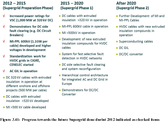
2015 – 2020
In the second half of the decade, the utilization of wind power is further developed building far shore (over 100 km) bulk power wind park clusters, which have power ratings in the range of some Gigawatts. At the same time the phasing out of coal fired and nuclear power plants continues [NBF – German and European are fools to phase out nuclear power]. Balancing generation and load calls for stronger system integration on a European level. To achieve the required flexibility of power flows and facilitate power trading, offshore wind parks are connected to one another and tapped into cross country links. A common European Grid Code is developed providing a basis for pan-continental system planning.
After 2020
This Phase is determined by continuing the system integration process leading to a European wide overlay grid. The overlay grid, mainly based on DC, is built to interconnect wind parks and pumped hydro storages in the North as well as large scale solar power plants in the South with the European load centres. Trans-continental power transmission is planned to connect to the solar power plants in the African desserts or to Eastern Europe and even Asia.
HVDC Technologies under development
DC circuit breakers
Today DC breakers or switches are commercially available even up to ultra-high voltage levels. However, they are working as transfer switches commutating the current from one circuit to another one. They do not have fault current interrupting capability.
DC fault current breaking functionality will be needed for larger HVDC grids to separate faulty parts of the grid during earth faults. It should be noted that most other faults can be handled by the converter itself or slower DC switches depending on the fault. DC breakers for HVDC grids need to handle fault currents with very fast rising times and operate without a natural current zero crossing as in AC applications. This has been shown earlier with full electronic breakers which operate very fast but have relatively high on-state losses. Recently, a hybrid DC breaker concept has been presented having a mechanical bypasspath to reduce the losses to near zero (60 kW at 320 kV DC) while maintaining clearance time within milliseconds [28]. For mechanical concepts, losses most likely will be even lower, but it still needs to be shown that the short clearing times needed can be achieved.
Transformation of DC voltages
Unless the Supergrid is specifically designed to operate at a common DC voltage and any schemes not at the common voltage are excluded, there will be a need to develop a DC – DC converter. This would be a device to convert one DC voltage to another, i.e. the equivalent of a transformer on an AC grid. The AC transformer has greatly facilitated the optimisation of AC transmission systems at different voltage levels(110kV, 220kV, 380kV etc) and their inter-connection to form AC grids. The DC equivalent would fulfil the same function.
In Europe there are many HVDC schemes inter-connecting different national grids and they have used a wide variety of DC voltages. Even for off-shore wind farm connection using HVDC, the first four schemes to be designed have all used a different voltage (±150kV, ±250kV, ±300kV and ±320kV). In the absence of a DC– DC converter, these schemes could only be integrated into a Supergrid by their AC connections.
DC – DC converters are a common device in industrial and commercial applications, i.e. they operate at low voltage and low power. However, the development of high voltage DC – DC converters is still at the academic stage of investigation or at the patent stage from some manufacturers. Technologies considered to date can be classified in two broad groups:
a) DC – AC – DC converters
The DC voltage is inverted to an AC voltage, typically at high (400 – 1000Hz), before being rectified to a DC voltage. This adds a power equipment stage between the converters. High frequency operation minimizes the physical size of the AC equipment, but impacts on losses. This scheme does introduce galvanic isolation between the two DC schemes.
b) Direct DC – DC converters Here there is no intermediate AC stage, the conversion only being achieved by power electronic converters, with some form of amplification circuitry. This adds to the complexity of the converter, but avoids the intermediate AC equipment, this potentially minimizing the size of the device. Whichever technology, or others not yet developed, is used a number of key functions will need to be achieved:
• DC voltage control (tap-changer function)
• Power flow control
• minimum operating losses
• compact footprint for off-shore and urban applications
• high reliability ( as a series device in the power flow)
• minimum maintenance requirement
• acceptable capital cost in comparison with converter station scheme costs
Such a device should also deliver some ancillary benefits, which should be available from its
design as a semi-conductor based converter.
• fault current limiting capability
• DC circuit breaker capability
If you liked this article, please give it a quick review on ycombinator or StumbleUpon. Thanks

Brian Wang is a Futurist Thought Leader and a popular Science blogger with 1 million readers per month. His blog Nextbigfuture.com is ranked #1 Science News Blog. It covers many disruptive technology and trends including Space, Robotics, Artificial Intelligence, Medicine, Anti-aging Biotechnology, and Nanotechnology.
Known for identifying cutting edge technologies, he is currently a Co-Founder of a startup and fundraiser for high potential early-stage companies. He is the Head of Research for Allocations for deep technology investments and an Angel Investor at Space Angels.
A frequent speaker at corporations, he has been a TEDx speaker, a Singularity University speaker and guest at numerous interviews for radio and podcasts. He is open to public speaking and advising engagements.