

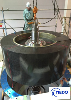
In 2015, Japan built the world’s largest-class superconducting flywheel power storage system with a superconducting magnetic bearings. The completed system is the world’s largest-class flywheel power storage system using a superconducting magnetic bearing. It has 300-kW output capability and 100-kWh storage capacity, and contains a CFRP (carbon-fiber-reinforced-plastic) flywheel. This flywheel is 2 meters in diameter and weighs 4 tons, and is rotated with a superconducting magnetic bearing at a maximum speed of 6,000 RPM. This is the world’s first superconducting magnetic bearing which uses superconducting material both for its rotor and bearing, and is capable of supporting heavy weight, although it is a compact-sized system.
The flywheel is made by stacking nine layers of CFRP rotors with a 2-meter outer diameter, 1.4-meter inner diameter and 10-centimeter thickness. With this method, flywheels of different storage capacities can be made by changing the number of layers.
It had grid-connection tests with a megawatt-class solar power plant at Komekurayama in Yamanashi Prefecture.
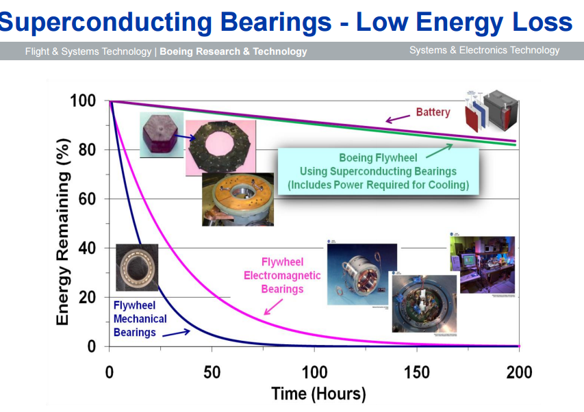
The superconducting magnetic bearing of this system uses a high-strength, high-temperature superconducting magnet made of a second-generation high-temperature superconducting wire material containing yttrium. The rotating shaft also uses high-temperature superconducting bulk. They succeeded in lifting the 4-ton flywheel without any contact by refrigerating the bearing to 50 K, that is, -223°C, and creating a powerful magnetic field. This technique has made it possible to rotate the flywheel at a highspeed, with less energy loss. Furthermore, since this system operates at significantly higher temperatures than 20 K or -253°C of the previous superconducting coil, the refrigeration cost can be reduced.
Boeing is also working on superconducting bearing flywheels. In 2012, Boeing flywheel tip speed was 800 m/sec. World record on small test rotor in 2012 was about 1,405 m/sec. FW tip speed is limited by material properties.
The Boeing plan was to develop new materials that would allow speed to reach 3,000 m/sec.
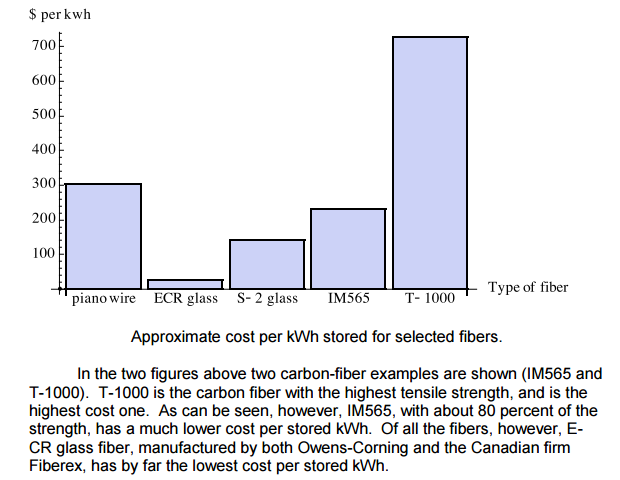
Boeing has the vision of combining advanced fiber technology and superconducting bearings to enable the development of a low-cost, extremely high energy-density, highefficiency flywheel energy-storage system. The superconducting bearings enable high efficiency and high spin rates. The new proprietary fiber enables high rotor tip speeds resulting in high energy density, with a projected cost of $100/kWh for the flywheel system at utility scale and large-rate factory production. The prototype flywheel will be small enough (7 kWh/5kW) to facilitate rapid development with a design that is easily scalable to a utility-size unit (~100 kWh) and amenable to factory production to achieve low cost. The vision for commercial production is that individual 100-kWh flywheels will be arrayed in a transportable container with a total storage of 2 MWh for utility applications

Power-thru uses magnetic levitation with no bearings.
All-composite rotors — versus steel hub and composite overlay — offer lighter weight and reportedly improve safety. The lighter weight also improves energy storage, as POWERTHRU explains: “Kinetic energy is roughly equal to mass times velocity squared. So doubling mass doubles energy storage, but doubling the rotational speed quadruples energy storage.” Thus, today’s all-composite rotors allow faster rotational speed (40,000 to 60,000 rpm), which increases short-term energy storage capacity.
(pdf) Flywheel Energy Storage for Automotive Applications – MDPI.com
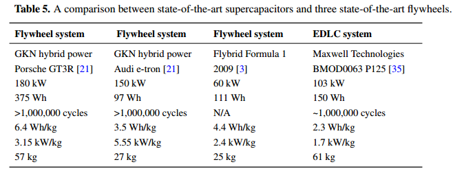
A 2015 review of flywheel energy storage technology was made, with a special focus on the progress in automotive applications. We found that there are at least 26 university research groups and 27 companies contributing to flywheel technology development. Flywheels are seen to excel in high-power applications, placing them closer in functionality to supercapacitors than to batteries. Examples of flywheels optimized for vehicular applications were found with a specific power of 5.5 kW/kg and a specific energy of 3.5 Wh/kg. Another flywheel system had 3.15 kW/kg and 6.4 Wh/kg, which can be compared to a state-of-the-art supercapacitor vehicular system with 1.7 kW/kg and 2.3 Wh/kg, respectively. Flywheel energy storage is reaching maturity, with 500 flywheel power buffer systems being deployed for London buses (resulting in fuel savings of over 20%), 400 flywheels in operation for grid frequency regulation and many hundreds more installed for uninterruptible power supply (UPS) applications. The industry estimates the mass-production cost of a specific consumer-car flywheel system to be 2000 USD. For
regular cars, this system has been shown to save 35% fuel in the U.S. Federal Test Procedure (FTP) drive cycle.
There are primarily four properties that make the flywheel attractive for use as energy storage:
• High power density;
• Long cycle life;
• No degradation over time and;
• Easily estimated state-of-charge.
There are four areas where batteries, for the time being, are decidedly better than flywheels:
1. Energy density;
2. Self discharge;
3. Steady output voltage;
4. Cost per kWh.


SOURCES – Energies, Furukawa, Boeing, Williams, Youtube

Brian Wang is a Futurist Thought Leader and a popular Science blogger with 1 million readers per month. His blog Nextbigfuture.com is ranked #1 Science News Blog. It covers many disruptive technology and trends including Space, Robotics, Artificial Intelligence, Medicine, Anti-aging Biotechnology, and Nanotechnology.
Known for identifying cutting edge technologies, he is currently a Co-Founder of a startup and fundraiser for high potential early-stage companies. He is the Head of Research for Allocations for deep technology investments and an Angel Investor at Space Angels.
A frequent speaker at corporations, he has been a TEDx speaker, a Singularity University speaker and guest at numerous interviews for radio and podcasts. He is open to public speaking and advising engagements.